
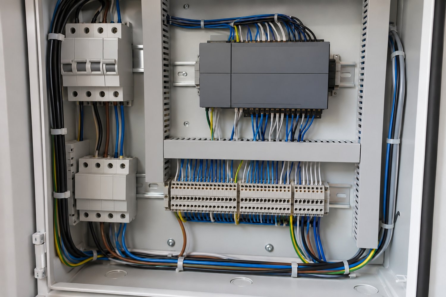
An industrial computer with a particular job
The programmable logic controller reference describes a PLC as a computer adapted for industrial control. It is intended for manufacturing equipment, assembly lines, robotic devices and other processes requiring reliable control and fault diagnosis. Its interfaces accept information from external equipment and send signals back to that equipment. The emphasis is therefore different from ordinary office computing: the program is closely connected to a process taking place in the physical world.
A PLC includes a processor, memory, a power supply, input and output interfaces, and communications equipment. Compact designs place the main functions in a common enclosure. Modular designs provide a rack or chassis for components selected for the application. A control system's size and required connections affect its physical arrangement. The programmable part describes the logic, while the equipment interfaces describe how that logic reaches the machine.
Why programmable control developed
PLCs developed in automotive manufacturing as an alternative to hard-wired relay control. Earlier arrangements depended on relays, timers and sequencers connected through wiring. Changing the process could require rewiring and careful revision of the documentation. Programmable control allowed changes to be expressed in a program while retaining equipment designed for industrial conditions. The distinction helps explain both the controller's purpose and the importance of a clear description of the intended process.
Early programming used ladder logic, a representation resembling relay-circuit diagrams. The connection made the program familiar to people accustomed to electromechanical controls. Other formats include function block diagrams, sequential function charts and structured text. These are different ways to express control relationships. Familiar concepts do not make programs interchangeable: the reference notes differences in input and output addressing, memory arrangements and instruction sets across controllers.
Inputs, the program and outputs
A sensor supplies information about a process condition. A simple digital input can indicate a switch state. An analog input can represent a variable such as pressure or temperature. Other inputs can involve positioning or machine-vision information. These are distinct kinds of information with different roles in a program. A controller must interpret the input according to the application, rather than treating every connected device as the same kind of signal.
The PLC repeatedly carries out a program scan: it reads inputs, evaluates the program and updates outputs. That description is a model of how information passes through the controller, rather than instructions for programming a live machine. The reference explains that remote input and output modules can add uncertainty to response time. The relationship between a detected condition and the output response is consequently part of the system's design.
Outputs can connect to indicator lamps, relays, motor equipment, solenoids or pneumatic and hydraulic cylinders. An actuator is the part that turns a control command into an action in the equipment. The controller does not become the whole machine simply because its program determines a response. Mechanical parts, electrical circuits and fluid-power equipment remain involved. Their integration is the subject of mechatronics and automation.
Controllers within a larger system
The industrial control system reference describes control equipment together with the instrumentation used for a process. Sensors measure process variables; control systems compare information with desired conditions and derive commands for final control elements, such as valves. A local controller can therefore be part of a larger system containing remote sensors, operator interfaces and other controllers.
Supervisory control and data acquisition systems gather information across equipment or separated sites. Distributed control systems coordinate control functions across a process. These arrangements can include PLCs. The reference identifies settings such as chemical processing, power generation and oil and gas processing. The terms describe system organization, rather than distinct versions of the same cabinet. A learner examining a process needs to recognize the local controller and the broader information and control arrangement around it.
The industrial internet of things reference describes sensors, instruments and industrial computing applications connected for data exchange and analysis. That adds a wider use for measurements already associated with equipment. The physical process, its control signals and its operating data are closely related, but they serve different purposes. The connection to process monitoring also appears in water and wastewater systems, where operating conditions, sample results and control equipment are parts of the work.
Control logic does not remove hazardous energy
Machinery must be isolated from hazardous energy before servicing under OSHA's lockout/tagout standard. OSHA describes the danger of unexpected startup and stored-energy release during maintenance. Electrical, mechanical, hydraulic, pneumatic, chemical and thermal sources can all be involved. A command in a controller program is therefore a different subject from the workplace's energy-isolation requirements.
OSHA assigns employers responsibility for hazardous-energy control and requires training appropriate to the employees' roles. The lockout/tagout reference likewise describes energy isolation as a condition before work begins. Understanding a scan cycle or reading a program does not qualify a person to service energized machinery. The working-safely discussion places these equipment responsibilities alongside the physical demands that technicians encounter.